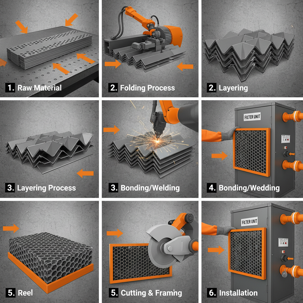


Defining precise custom rfi emi shielding specs is critical for engineers managing electromagnetic interference in high-precision environments. In the specialized field of metal honeycomb manufacturing, shielding specifications determine how effectively a component blocks radio frequency interference (RFI) and electromagnetic interference (EMI) while maintaining necessary airflow or structural integrity.
Many procurement teams struggle with the trade-off between shielding effectiveness and ventilation. When specifications are too vague, the resulting components may fail compliance tests or restrict critical airflow, leading to equipment overheating or signal degradation in aerospace, automotive, and marine testing systems.
This technical analysis provides a comprehensive framework for establishing shielding specifications, evaluating material performance, and selecting the appropriate honeycomb configurations to ensure optimal electromagnetic compatibility (EMC) for industrial applications.

Fundamental Components of Shielding Specifications

A complete set of custom rfi emi shielding specs must go beyond simple dimensions. The core of any shielding requirement is the attenuation value—the measure of how many decibels (dB) of signal are blocked across a specific frequency range. Specifications must clearly define the start and end frequencies (e.g., 10MHz to 18GHz) to ensure the waveguide-beyond-cutoff principle is correctly applied to the honeycomb structure.
Beyond frequency, mechanical specs must include the precise cell size and wall thickness. For instance, Hengshi provides customizable cell sizes such as 10mm and 20mm, which directly influence the cutoff frequency of the EMI vent. These dimensions must be paired with tight tolerances to prevent "leaks" at the seams where the honeycomb core meets the outer frame.
Impact of Honeycomb Cell Geometry on Attenuation
The efficiency of an EMI shielded honeycomb vent relies on the relationship between the cell diameter and the wavelength of the interference. When the cell size is significantly smaller than the wavelength, the honeycomb acts as a waveguide that is "cutoff," effectively reflecting the electromagnetic waves while allowing air to pass through. This is why defining the cell size is the most critical part of the technical specification.
Increasing the depth of the honeycomb panel generally improves attenuation, provided the cells remain straight and uniform. If the cells are distorted during the stamping or welding process, the shielding effectiveness drops significantly. Precision manufacturing, such as the independent honeycomb stamping and welding equipment used by Hengshi, ensures that the geometric integrity of each cell is maintained to meet strict RF specs.
Material Selection for Harsh Testing Environments
Material choice is a primary driver of both shielding performance and long-term durability. While aluminum is common for lightweight applications, SUS 304 stainless steel is preferred for environments where corrosion resistance and structural strength are paramount. Stainless steel honeycombs are particularly effective in humid industrial conditions or chemical-rich testing environments where aluminum might oxidize and lose conductivity.
The conductivity of the material influences the reflection coefficient of the shield. High-grade SUS 304 offers a balance of durability and EMI blockage. When specifying materials, engineers must also consider the brazing and welding technology used to join the honeycomb to the frame, as any gap or non-conductive joint can create a "slot antenna" effect, allowing RFI to penetrate the shielded area.
Comparing Shielding Effectiveness Across Configurations
Shielding effectiveness is not a static number but a relative value based on the configuration of the vent. As cell size increases, the cutoff frequency drops, meaning larger cells allow lower-frequency interference to pass through. The following illustrative framework demonstrates the relative attenuation performance (represented as a normalized score) of different cell configurations against common frequency bands.
The chart indicates that while smaller cell sizes provide superior attenuation (higher scores), they increase airflow resistance. This conceptual comparison highlights why a custom approach is necessary: a 3.2mm cell may be perfect for high-frequency blocking, but a 10mm cell is required when high-volume airflow is the priority for wind tunnel applications.
Integrating Shielding with Airflow Management
A common engineering failure is optimizing for EMI shielding while ignoring laminar flow. In aerospace and automotive wind tunnels, the honeycomb must act as both an EMI shield and an air flow straightener. If the cell walls are too thick or the brazing is uneven, turbulence is introduced, which compromises the accuracy of aerodynamic data. Precision flow management requires a balance between the wall thickness needed for shielding and the open area needed for air passage.
To achieve this, custom rfi emi shielding specs should include "Open Area Percentage" as a key metric. By utilizing high-precision CNC processing and vacuum brazing, manufacturers can create panels that maintain a rigid, lightweight structure without obstructing the flow field. This integration is essential for vehicle development and spacecraft design where fuel efficiency and aerodynamic performance are measured in minute increments.
Common Specification Errors and Risk Mitigation
One of the most frequent mistakes in procurement is specifying a "general" EMI shield without defining the frequency range. Because honeycomb vents act as high-pass filters, a shield that works at 10GHz may be completely transparent at 1GHz. To mitigate this risk, engineers should provide a target attenuation curve rather than a single dB value.
Another risk is neglecting the installation interface. Even a perfectly manufactured honeycomb panel will fail if the mounting flange is not properly grounded to the chassis. Specs should explicitly state the requirements for the perimeter seal or the use of honeycomb sealed strips to ensure a continuous electrical bond between the shield and the enclosure, preventing leakage at the edges.
Decision Framework for Custom EMI Vent Procurement
When evaluating suppliers for custom rfi emi shielding specs, the decision should be based on a matrix of material capability, precision of equipment, and application experience. The following table compares three common technical approaches to EMI ventilation to help buyers identify the best fit for their project.
| Approach | Shielding Level | Airflow Impact | Best Application |
|---|---|---|---|
| Small Cell Alu | High (HF) | Moderate | Lightweight Electronics |
| Large Cell Alu | Moderate | Low | General Ventilation |
| Stainless Steel (304) | High/Stable | Moderate | Industrial/Marine |
| Hybrid Coated | Very High | Moderate | Medical/Laboratory |
| Thin Wall Steel | Moderate | Low | Automotive Tunnels |
| Custom Mesh/Core | Variable | High | Specialized RF Labs |
Based on this framework, users requiring maximum durability in corrosive environments should prioritize SUS 304 stainless steel, while those focusing on high-frequency attenuation in weight-sensitive aerospace projects should lean toward precision aluminum configurations.
Frequently Asked Questions
Cell size is determined by the cutoff frequency of the interference you need to block. Generally, the smaller the cell, the higher the frequency it can block. You must identify the lowest frequency of the RFI you are concerned with and calculate the maximum allowable cell diameter to ensure that frequency remains in the "cutoff" zone.
EMI (Electromagnetic Interference) is a broad term covering all electromagnetic disturbances, while RFI (Radio Frequency Interference) specifically refers to the higher frequency range. In honeycomb panels, the physical structure handles both, but the specifications for RFI often focus more on specific GHz ranges and waveguide theory.
Yes, provided the geometry (cell size and wall thickness) is the same. While aluminum has higher electrical conductivity, stainless steel 304 is often preferred in industrial specs due to its superior mechanical strength and corrosion resistance, which prevents the shield from degrading over time.
Increasing the thickness (depth) of the honeycomb core generally improves the attenuation of the signal. A deeper cell creates a longer path for the wave, increasing the loss as it travels through the waveguide, which results in better overall shielding performance.
It is a principle where the dimensions of the honeycomb cell are small enough that electromagnetic waves below a certain frequency cannot propagate through the cell. The cell acts as a wall to those waves while allowing air to pass, effectively creating a ventilated shield.
Ensure the specification includes a high-quality conductive bonding method. This typically involves using honeycomb sealed strips or precision-welded flanges that create a seamless electrical contact between the honeycomb core and the surrounding metal enclosure.
Conclusion
Developing accurate custom rfi emi shielding specs requires a deep understanding of the relationship between material science, waveguide geometry, and airflow requirements. By prioritizing precise cell dimensions, selecting durable materials like SUS 304 stainless steel, and accounting for installation grounding, engineers can ensure their systems remain compliant and interference-free without sacrificing necessary ventilation.
For organizations evaluating implementation options for high-precision shielding vents, detailed technical resources and product capabilities can be reviewed at www.hengshihoneycomb.com to ensure the chosen configuration matches the specific frequency and environmental demands of the project.